
Project – Time Reversal Detection and Imaging in Electromagnetics
Project Description: this project aims to study time reversal detection algorithms, using a single antenna pair, or an array of antennas to improve radar detection.
About Time Reversal
Time reversal techniques obtain increased resolution by exploiting scattering and multipath in propagation through inhomogeneous channels. Time reversal was used by French physicist Fink and his collaborators to achieve super-resolution focusing in acoustics, [Fink, Prada, Wu, Cassereau, 1989, Fink, 1997] as demonstrated by their work with controlled ultrasonic experiments in water tanks. Later, large-scale acoustics experiments in the ocean confirmed the resolution ability of time reversal, [Kuperman, Hodgkiss, and Song, 1998,Song, Kuperman, Hodgkiss, Akal, and Ferla, 1999].
In classical matched field processing (MFP), in the acoustical domain, (e.g., Baggeroer, Kuperman, Mikhalevsky, 1983), detailed modeling of the channel is used to predict the field as received by an array of sensors, after the wavefield propagates through an inhomogenous channel. MFP, in simple terms, solves an inverse problem (source detection or localization) by stepping through a sequence of forward problems, where in each forward problem the unknown location of the source is postulated at each one of potential positions. Practical implementation of MFP implies the solution of the wave equation for each forward problem assuming a given channel velocity propagation profile and given boundary conditions. This is computationally demanding and requires good knowledge of the environmental conditions, both of which make MFP an expensive, sensitive solution for many practical problems. Time reversal provides a very good alternative to MFP, since it avoids the detailed modeling of the channel, while still providing the potential gain from matching to the propagated field, rather than matching to the original transmitted wavefield. In a sense, time reversal provides the actual channel Greens’ function, in contrast with MFP where the channel Greens’ function is computed from the model.
Potential applications of time reversal techniques include ultrasound and biomedical applications, underwater acoustics, synthetic aperture radar, imaging through walls, grounds or forests where signals are widely spread.
Time reversal detection and imaging in electromagnetic domain
In our work, we study detection and localization with time reversal in the electromagnetic (EM) domain. Our targeted application is radar system. A radar is a sensing device that provides target information, such as, range, radial velocity, angular direction, size, and shape, by radiating electromagnetic energy and utilizes the echo scattered from a target. Without a direct line of sight between the radar and the target because of a rich scattering environment such as forrests and walls, the returned radar signals have a significant time spread, thus the conventional matched filter works poorly and the radar performance degrades. Time reversal takes advantage of the rich scattering environment, illuminates the target area with the time-reversed returned echo to adaptively cancel interfering signals and to focus on targets.
We focus on two types of problems using time reversal: detection and imaging. We develop the theories and algorithms and carry out experiments to verify our analysis.
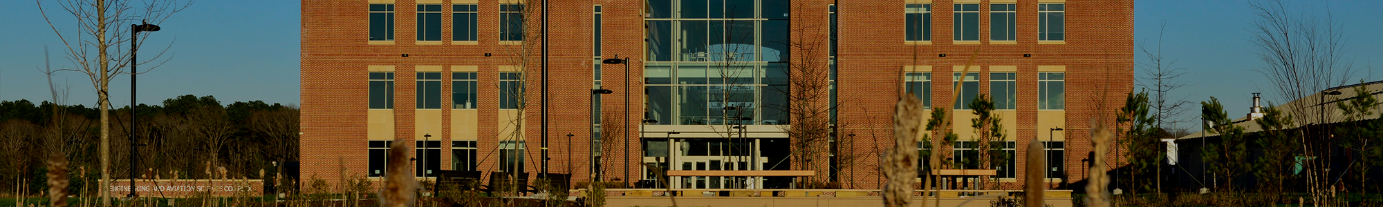
Figs.-1 show two pictures of the time reversal imaging lab. The scattering environment is created by placing potted trees and pipes around the target area. The electromagnetic measurements are recorded using two horn antennas with 2 GHz bandwidth. The time reversal is done in three steps: 1) we probe the clutter channel. For a stationay channel, we can learn it accurately; 2). we learn the channel when a target is present. The clutter channel can be subtracted out due to our knowledge of the clutter channel in step-1; 3). we time reverse (or phase conjugation in frequency domain) the residue signal, normalize the energy, and send it back to the environment. Once we receive the echoes. we subtract out the clutter component and process the resultant signal for detection and localization.
Figs.-2 show the detection results using a pair of antennas, one for transmitting and one for receiving. We study 3 detectors: time reversal generalized likelihood ratio detector (TR-GLRT), energy detector (ED) and matched filter (MF). In a rich scattering environment, time reversal detection provides a superior performance compared with conventional method. From a signal processing perspective, time reversal optimizes the transmitting waveform that best matches the target response. It provides a better transmission efficiency and results in a better signal to noise ratio at the receiver.
Figs.-3 depict time revesal imging results using a pair of linear antenna arrays. A copper target is masked by trees. Each linear array of 5 antennas has an inter-element spacing of 10 cm. Letters indicate the center of potted trees. The cross denotes the exact location of the target while the circle denotes the peak of the images. The closer the circle to the cross is, the better the localization accuracy is. For each image, the total range of the color bar shows the dynamic range of the imager. For visual comparison purposes, the images are properly scaled to the same range in (0 ~ -31) dB. The sharper high contrast images provide better details, and thus better resolution. The time reversal imager (TRAIC+TR beamformer) adaptively cancells out the interference and focuses on the target. The conventional imager (Direct Subtraction beamformer) subtracts out the clutter component and applies beamforming directly. From the images we see that the time reversal imager produces a better resolution and a better accuracy compared with the conventional method.
 |  |
Fig.-1: Photos of electromagnetic measurement in time reversal imaging lab. Left figure: two horn antennas point to the center of the target area. The target is a copper pipe surrounded by 8 potted trees and a few copper pipes as scatterers. The operational frequency range is 4GHz to 6 GHz with the center frequency of 5 GHz. . Right figure: two horn antennas are placed on two position slices, each is connected through a cable to a network analyzer. The trees and the copper pipes create a scattering environment. The blue wall is the absorber wall.
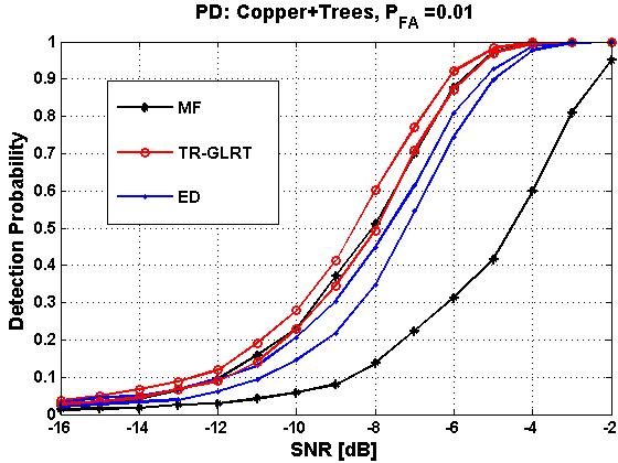 |  |
Fig.-2: Single antenna detection using time reversal. The target is a copper pipe in a scattering environment that consists of 8 potted trees and 6 copper pipes. The electromagnetic field data are collected using two horn antennas, one for transmitting and one for receiving, at 10 positions along two separate tracks. Thus, each horn antenna points to the center of the target area with 10 look angles. The collected 100 channels characterizes the Green’s functions of the target and the scattering environment. The above two figures depict the best and worse performance curves (probability of detection) using these 100 channel data. Left figure — probability of detection curve using time reversal. TR-GLRT is the generalized likelihood ratio test using time reversal (red). ED is the energy detector (blue), and MF is the matched filter (black). TR-GLRT shows the best performance among these 3 detectors. MF appears to be very sensitive to the channels due to different scattering characteristics. Right figure — detection probability with a single copper target, with no scatterers. MF (black) shows the best performance as we predicted. TR-GLRT is slightly better than ED.
 | 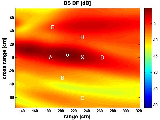 |
Fig.-3. Time reversal imaging results using beamforming. The imaged area is in -65 cm to +65 cm in cross range, and 135 cm to 320 cm in range. The target is a copper pipe surrounded by trees. The letters (A, B, C, D, E, H) indicate the locations of the trees, the circle is the peak of the image, and the cross indicates the exact location of the target. The dynamic range of the image is 30 dB. Left figure–Imaging using time reversal for adaptive interference cancellation and target focusing. Right figure — Imaging using conventional method. The time reversal method appears to have a better resolution and accuracy compared with the conventional method.